Data Encapsulation
The OSI Model and Encapsulation
As data moves from the application layer and begins to move data it goes through a process called encapsulation. Encapsulation is when we take a large portion of data and it gets put in to smaller pieces of data into virtual envelopes and adding addressing information onto it.
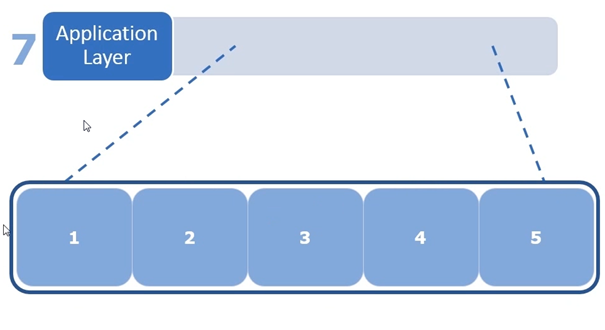
So if we for example visit google.com, google.com will send its webpage back to us which are nothing more than a file. Before google can send that data is going to be in a large chunk of information and it’s going to be sitting at the application layer (layer 7), remember Http operates at the application layer. When the data is collected it is sent from the application layer down to the transport layer.
The blue large box represents the large chunk of data sent from the application layer which is being sent from google to our workstation. The smaller blue boxes represent pieces of data broken up into smaller pieces, which are going to be sent to the Transport layer.
Once the smaller pieces are sent to the Transport layer they are encapsulated in the transport layer or if you like the transport layer envelope. The following screenshot shows the first chunk of data being put into the envelope. Then the transport header is added, the transport header has the following information
Source port
Destination port
Other information which is going to be protocol specific, for example if we are using TCP it’s going to have windows sizes, acknowledgement numbers as well as other information which will make the transport layer operate properly when using the TCP protocol. If we are using another transport protocol such as UDP it will be included in the “other info field” in the transport layer header.
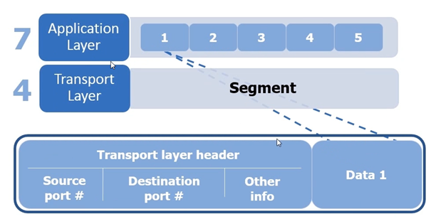
When the data has been encapsulated it becomes a segment. Once the Segment has been created it is handed down to the network layer.
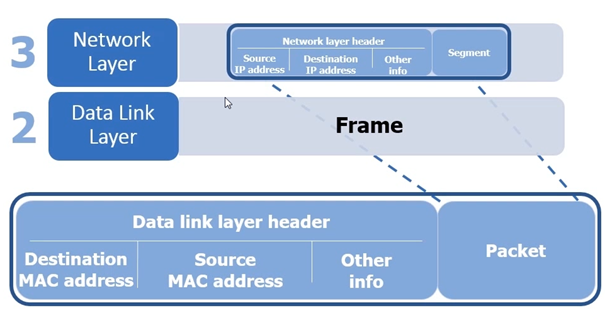
When the segment has been passed to the Network layer (Layer 3) it is again put in an envelope. The Envelope is the called a Packet. Inside this packet it the source IP address and destination address is added and other information to make the internet protocol work. So the packet becomes the segment plus the network layer header.
Once the packet has been created it is sent to the Data link layer where it is once again put in an envelope (see following screenshot). Once the packet is in the envelope the data link header is added, the MAC address destination and MAC address source is added as well as other information that’s related to the layer 2 network. The encapsulated packet with the Data link header is now known as a frame.
Once the frame has been created it is then sent to the Physical layer. The physical layer converts the frame into pulses of light or electrical signals or radio waves / photons, which are basically interpreted as 1s and 0s being translated over the physical media wire, wether it be copper cable, fiber or WLAN.
When the device at the other side receives it will reassemble it frame and determine what to do with it. When the devices has determine the frame is for its device it will extract the packet, then it will examine the packet, when the packet is examined it will extract the segment out of the packet, the segment will then be interpreted and sent to the the proper process at the application layer.
This encapsulation and de-capsulation is at the core of data networking, and its really important to understand the process for troubleshooting network issues at different layers of the OSI network model.
Here are some examples of problems
Data link layer problem it’s going to be related to the network Interface cards in switches.
Network layer problem it’s going to be related to IP addressing and Routers.
Transport layer problem its going to be related to port numbers and firewalls.
Application layer problem it could be related to the service on the server.
OSI model and protocols at each layer
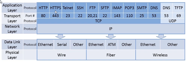
Using the above screen shot we can see protocols being used at the application layer, underneath the protocols we can see the ports used at the Transport layer. It’s pretty straight forward, however if you look carefully SFTP uses port 22, but SSH also uses port 22, in this case we are using FTP in the core process but it’s encapsulated in a SSH session which encrypts the FTP session, so SFTP is really port 20, 21 and 22.
If you look at the first protocols from HTTP to DNS you can see that they are using the TCP protocol. Most application protocols today use the TCP Protocol.
The last 2 protocols on the previous screenshot highlighted in light blue ‘DNS and TFTP at the application later are using the UDP protocol at the transport layer. TFTP was designed as a lightweight protocol it doesn’t use all the overhead that’s used with TCP. Same with DNS, but sometimes it’s going to use TCP for reliability.
So you can see that all the protocols are at the application layer and the transport layer are going to make use of the IP protocol at the network layer. So the network layer becomes this unified body to encapsulate any application layer traffic and any transport layer traffic that can be transferred across the network.
Now to move the packet from one side of the network to another network especially across long distances we will be traversing a very long distance through quite a few different organizations we might see many different type of datalink layers being used. So if we are using a physical wire we might be using Ethernet or Serial (Wire), Ethernet or ATM (Fiber) or Wireless Ethernet. So when Encapsulating is done using the IP protocol we can move it over any type of medium we want
So to understand what’s going on let’s take a look at our home network in the following screenshot.
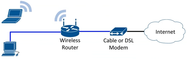
So if you requested a website such as www.google.com and hit enter it would setup the request at the application layer
It would send it down to the transport layer to get formatted into a segment
Then it would send it down to the network layer and format it into the packet
The packet would be then encapsulated in to with wireless Ethernet to communicate with the WLAN router. So the wireless notebook will put the IP packet into a wireless IP Frame and then send the over wireless Ethernet frame to the wireless router
The wireless router then will extract the IP packet from the frame and build a new frame using wired Ethernet to send that frame from the wireless router to the cable modem.
The cabled modem will then take the packet it out of the wired Ethernet frame and put it into a new frame which is called a DOCSYS frame and the DOCSYS frame can be sent from the cable modem into the internet to your internet service provider.
From your ISP the IP packet is extracted from the frame and again encapsulated.
And the process goes on till the frame reaches the requested location.
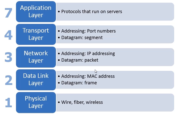
So wrapping up the OSI Model
Application layer – Protocols that run on servers
Transport layer – Port numbers – Segment
Datalink layer – MAC address – Frame
Physical – Fiber – Wireless
The OSI model is important to understand … learn practice and practice …